SoleMates: Upper
With 1.4% of CO2 emissions coming from the shoe industry and each shoe taking approximately 30 to 40 years to decompose, it is evident that shoe production is bad for the environment. As a solution, SoleMates is a shoe made of sustainable materials with removable and replaceable outsoles. The aim of SoleMates is to reduce the CO2 emissions and pollution that come from the shoe industry, while also making it accessible to many. The upper of SoleMates is designed to be durable, comfortable, and fashionable, all while being made with sustainable materials.
PROBLEM IDENTIFICATION
To start off the problem identification for the upper of SoleMates, research was done to obtain insight on what users are looking for in the upper. The upper of a shoe includes the tongue, top line, counter lining, eyelets, toe cap, and collar (shown in image). By talking to peers, friends and family, it was found that users are looking for comfort (in the sense of adjustability and supportiveness), stylish yet versatile/practical designs, durability, and cleanability. Along with this, users want the upper to be made out of quality materials. With this in mind, the following problem statement and project objective was created: How can we create an upper that is durable, comfortable, accessible, and fashionable in a sustainable way?

PHASE ONE MECHANISM IDEATION
When research was done on the accessible shoes that are currently on the market, it was realized that while the most popular mechanisms out there are zippers, velcro and elastic laces. However, most of these mechanisms take away from the overall aesthetic of the shoe. Wanting to ensure this doesn’t happen, some brainstorming sketches were developed to explore the different accessibility mechanisms that could be incorporated into the design.
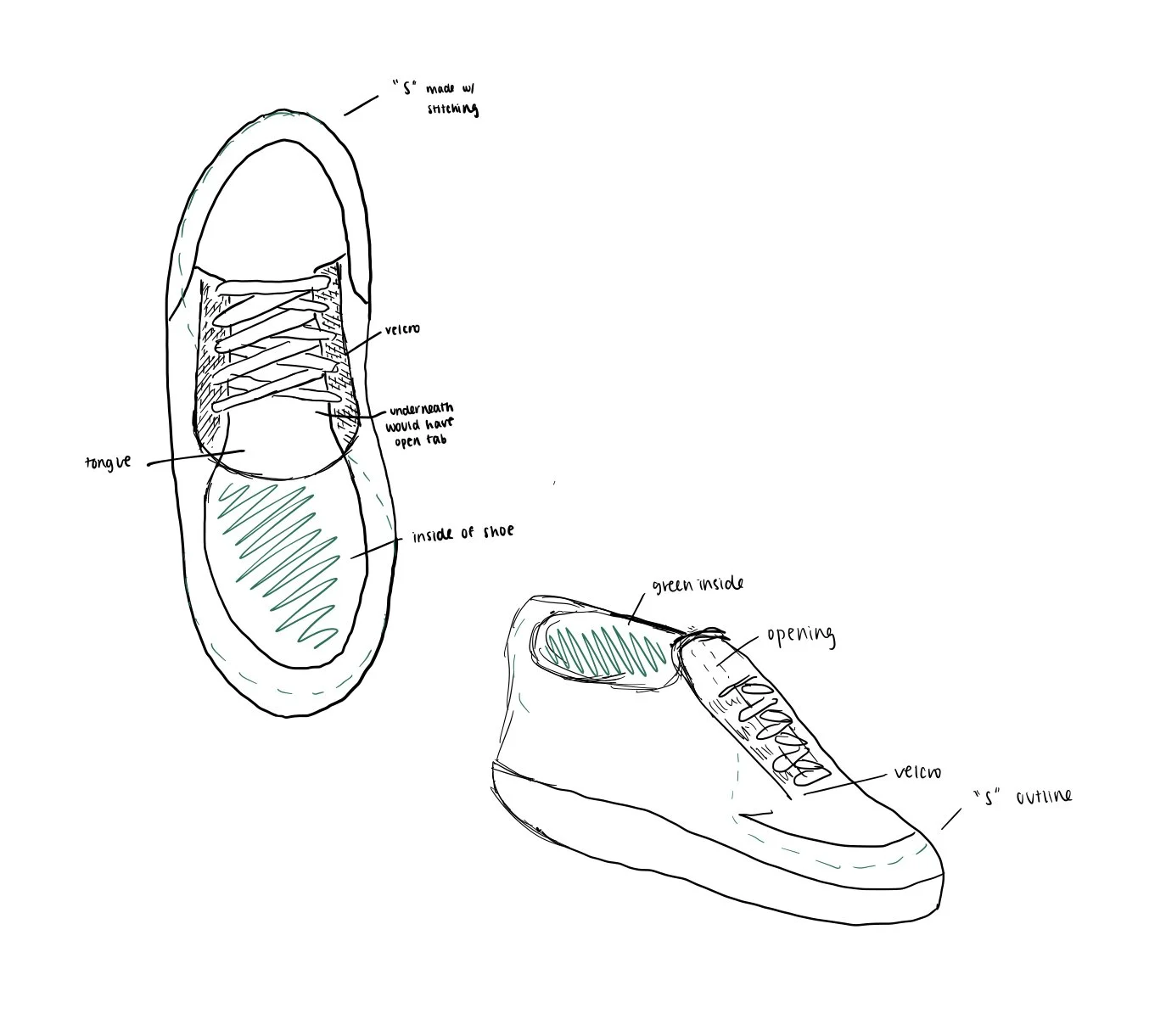
This first ideation (inspired by shoes currently on the market) involves velcro while having an opening in the middle for users to easily slip on and take off their shoe.
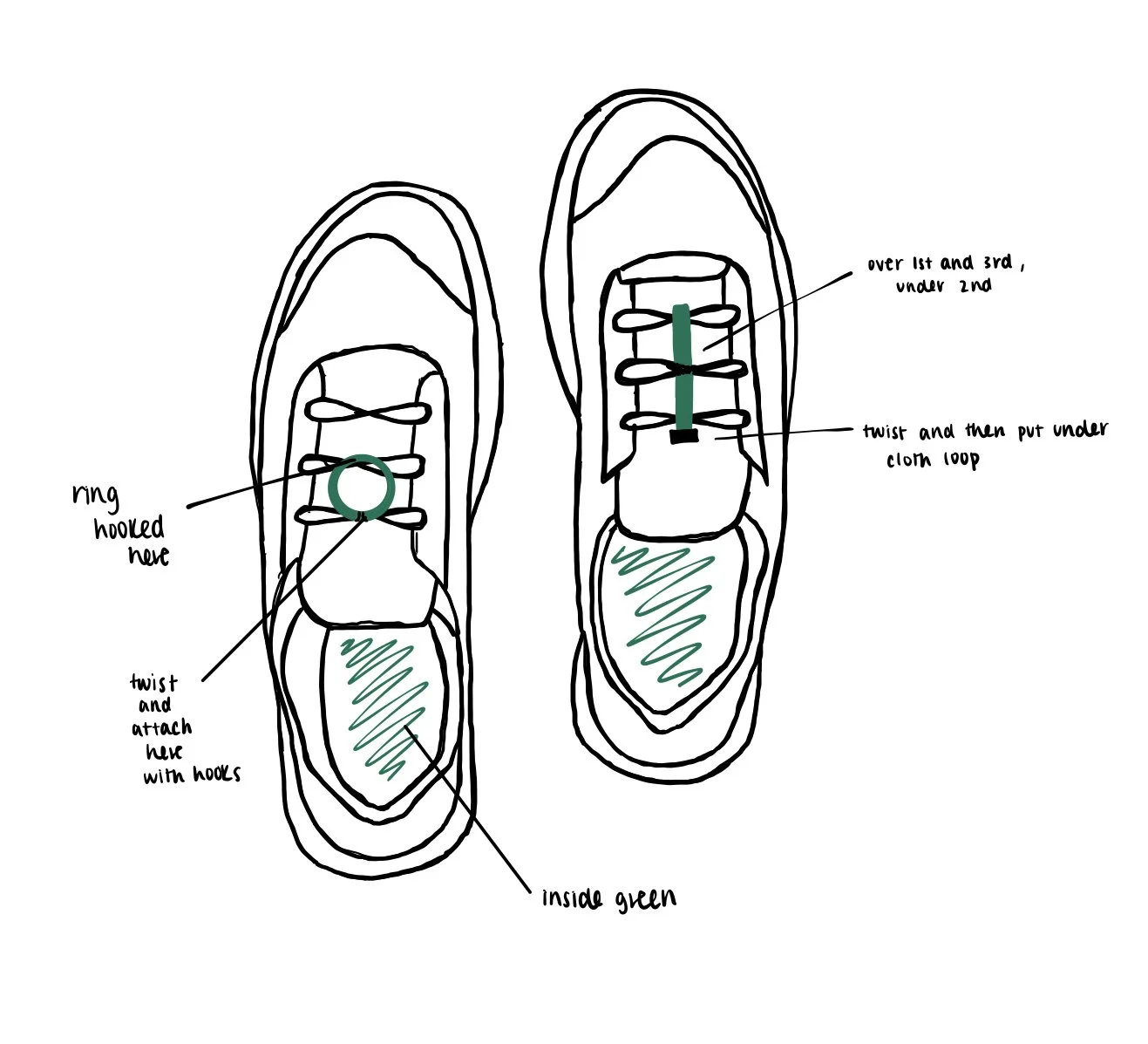
For this next ideation, the team focused on an accessibility mechanism that represents an alternative way to tighten laces. The first one incorporates a ring that will be looped through the middle lace and then twisted and hooked onto the top lace. The second one uses a stick that goes over the first and third laces, while under the middle. From here, it will be twisted and placed under the cloth loop.
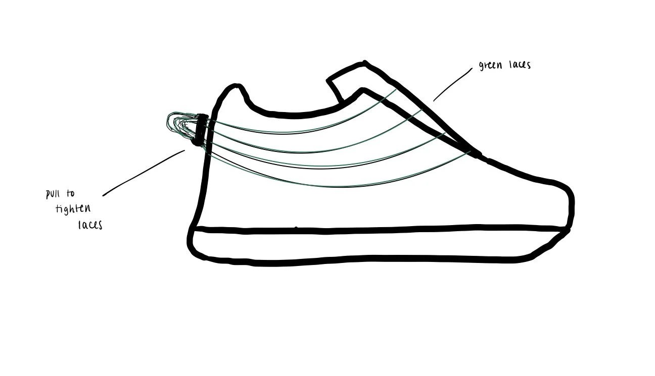
This ideation incorporates a series of laces that will be placed loosely around the shoe with a drawstring-like mechanism. The loose laces allow the user to easily slide their foot in and the mechanism itself can be used to tighten the laces to secure their foot.
PHASE ONE MECHANISM PROTOTYPING
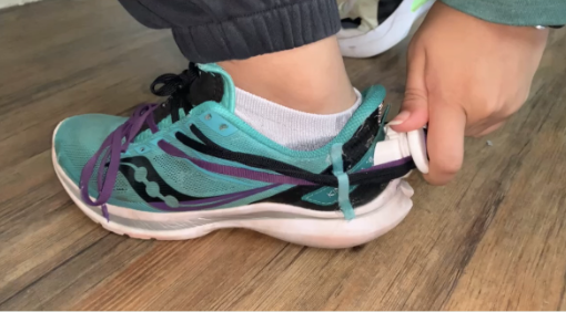
To start off this process, the team wanted to test the different accessibility mechanisms to see which one(s) would be the best. Three sneakers were modified by cutting off the sole and adding a vertical cut to the heel to accommodate for any sized foot. Pipe cleaners were then added to the bottom and back in a way that they could be tightened around the tester's shoe.
For the Velcro mechanism, the laces were taken out so that the velcro could be attached to the sides of the tongue and the underside of the eyelets where the laces were previously. This created a large opening for the foot to slide in.
To create the Ring Twist mechanism, the laces were tied very loosely so that the user could easily slide their foot in and out of the shoe. Then a ring with a diameter of 2 inches was looped under the laces at the middle of the shoe. By twisting this ring, the laces twisted around each other and pulled the shoe tight.
Using the same shoe to make the Stick Twist mechanism, the ring was just swapped out for a popsicle stick. This design was very similar to the previous one. The stick was inserted under the middle laces and then twisted to tighten. Once tight, the stick could then be slipped under the laces at the top or bottom to secure it in place.
The Drawstring mechanism consisted of four separate laces that were threaded through the eyelets and then wrapped around to the back of the sneaker. A cord lock (represented in the rough prototype as a rubber band) was added to the laces at the back of the shoe. To tighten this prototype, the user would pull the laces from the back, and push the cord lock forward.


THE FINAL PHASE ONE MECHANISM PROTOTYPES:


Based on user feedback and asking users to rank each mechanism 1-4 with 1 being the most favorite and 4 being the least, it was clear that the Drawstring design was the most favorable. This is due to the fact that users felt secure with this mechanism and also liked its visual aesthetic. However, one issue that came up was the extra laces that would hang from the back of the shoe. Many users thought that this could pose as a safety issue. As a solution, since the Ring twist mechanism was the second favorite of many, the team thought to combine these two ideas.
PHASE TWO MECHANISM IDEATION
As a result, the next ideations that were created had the same aspects to the Drawstring design except with another component added to the back of the shoe to get rid of the extra hang of the laces.
The first ideation combined the Drawstring mechanism with the Ring Twist mechanism. The only difference with this new Ring Twist mechanism versus the previous one is that once the loop is twisted, there would be an attachment that the user would be able to click the loop onto.
The second ideation incorporated a knob at the back of the shoe. The laces would go into the mechanism and as the knob is turned, the shoe tightens around the user’s foot. This mechanism would possibly be more accessible to those who do not have fine motor skills in their hand as the knob can be turned with the user’s palm as well.


PHASE TWO MECHANISM PROTOTYPING
This second phase of prototyping can be separated into the two previously mentioned ideations: the Loop mechanism and the Knob mechanism.
To start off with the Loop mechanism, a CAD rendering was made in Fusion 360. The tolerances of the loop and the attachment were adjusted so that there would be a nice click when they came together. An opening was added to the bottom to account for the laces that would be there when the loop is twisted.
Once the rendering was done, it was 3D printed and attached to the shoe with hot glue. The laces were wrapped around the shoe in a similar way to the previous Drawstring mechanism. From there, the laces were put through the loop. The loop was then turned and then clicked on to the attachment.
For the Knob mechanism, the mechanism was similarly designed in Fusion 360. A knob was added that could easily be turned to tighten the shoe. A button was also added to the top of the mechanism for a quick release. The laces would be threaded through the knob.
After this, the rendering was 3D printed and attached to the shoe in a similar way to the Loop mechanism with hot glue. The laces were wrapped around the shoe with guides that led the laces to the mechanism. With the laces wrapped around the mechanism, the knob could be turned in one direction to tighten them and turned in the opposite direction to loosen.


THE FINAL PHASE TWO MECHANISM PROTOTYPES:

Based on the user feedback, it was clear that the Knob Mechanism was more favorable due to it being easier to tighten and secure. However, for the next iteration of this mechanism, improvements will be made so that the mechanism is more compact, a casing will be added around the spool (the device that laces wrap around when the knob is turned), and the release button will be removed to simplify the mechanism. Instead of this release button, the user would just have to turn the knob in the opposite direction to loosen the laces.
HIGH FIDELITY UPPER PROTOTYPING
SHOE
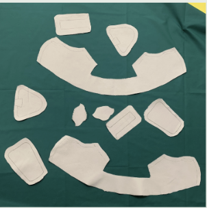
To start the high fidelity prototyping process, lasts (a foot mold that is used to shape the shoe) were created. These lasts were made using cardboard based off of a Men’s Size 11 shoe. Layers of cardboard were placed on top of each other, each piece getting a little smaller in size as the layers increased. After this, came making the pattern. To help, a Men’s Size 12 sneaker pattern was obtained and changes were made where needed to adjust the size to a Size 11. Once the pattern was done, the team moved onto tracing the pattern onto the canvas and green fabric. These pieces were then cut out so that the sewing could start.
For the sewing, the canvas and green fabric were both individually sewn. From here, these materials were both flipped inside out and then sewed together at the top. At this point, some adjustments were made to the pattern to account for the drawstring design of the laces. Guides were added to the sides of the shoe by stitching another piece of fabric to the main piece. The tongue of the shoe was filled with pulled apart cotton to add comfort and support before being attached to the shoe. Next, four eyelets were added to each side of each shoe. This was done by hole punching the canvas and then hammering in the eyelet.


MECHANISM
The mechanism was created through many iterations, each 3D printed and then tested. A case for the spool was added to contain the laces. However, the laces would still get tangled, so, in a later iteration, holes were added to the case to guide the laces into the spool. Throughout these iterations, the mechanism was compacted. The ratchet mechanism originally had a release mechanism, but due to complications with fabrication as well as usability, the release button was removed. The ratchet was then adjusted so that it could be twisted in both directions (to tighten and loosen the shoe). And lastly, to enhance the usability and comfort of this mechanism, grips were added on the knob.

ASSEMBLY OF SOLEMATES & FINISHING TOUCHES
Once the material of the shoe was sewn together, it was time to shape the shoe and connect it to the sole. The green fabric was first wrapped around one of the lasts tightly and glued to a piece of cardboard. Once dried, the sewn canvas was pulled tightly around the green fabric and last and glued it. In the back of the shoe, a piece of a foam sheet was placed between the green fabric and the canvas for additional support to the structure of the shoe. After this dried, the connection piece of the sole was glued to the bottom of the shoe. This process was then repeated for the second shoe and the glue that was used was contact cement. Next, the final ideation of the mechanism was added to the back of the shoes with glue. Many different ways of lacing the shoe were explored, sometimes using multiple laces in one shoe or different patterns. Eventually, the team found one that worked for the prototype. Later, it was found that a thinner lace (represented by a string in this project) seems to work better. Finally the lasts were removed and the shoes were complete.
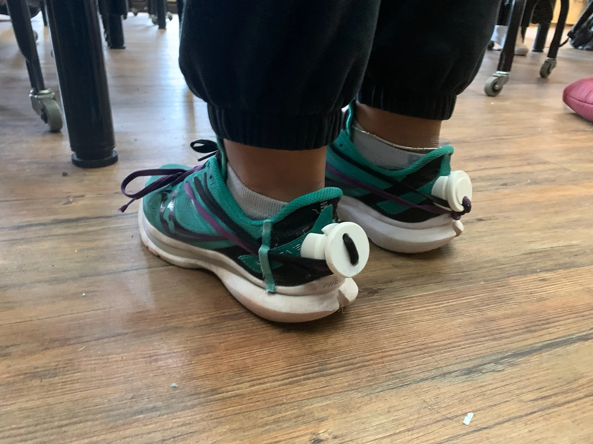
THE FINAL HIGH FIDELITY PROTOTYPE:


To learn more about the design and prototyping process for this project, please visit this link: https://docs.google.com/document/d/1ewMQSS2OK779KL6XNJYWd7JXZgzNvCEGkvI5LF6o5oM/edit?usp=sharing