Aerial Flame Force
Imagine a world where fires are fought by autonomous drones and the loss of human life due to wildfire fighting has been reduced to zero. With the Aerial Flame Force, the hope is that the wildfires can be extinguished early on rather than later when it has spread. Additionally, these can be used to create fire lines which would be a proactive way to aid in firefighting. Using considerations from the U.S. Forest Service and customer interviews, the team created a drone that comprehensively achieves all needs.

PROBLEM IDENTIFICATION
Establishing a problem space and truly understanding why creating this product would be so beneficial was the first step of the project. Our research uncovered that according to the National Oceanic and Atmospheric Administration, climate change has caused drought, increased heat, and a dry atmosphere that greatly increases wildfire risk in the western United States. In other words, the conditions that climate change causes are almost all directly linked to favorable wildfire conditions (National Oceanic and Atmospheric Administration, 2022). The U.S. Forest Service, a branch of the U.S. Department of Agriculture (USDA) has employed 11,187 wildland firefighters as of 2023, but they admit that “this isn’t enough capacity to meet the needs of the ongoing wildfire crisis” (Wildland Firefighting Workforce, 2023). None of these facts change how dangerous wildland firefighting is, as 170 firefighters have died between 2007 and 2016 while fighting wildland fires (A Publication of the National Wildfire Coordinating Group NWCG Report on Wildland Firefighter Fatalities in the United, 2007).
This led to the creation of the problem statement and the project objective: Due to the combination of frequent wildfires, the lack of funding and the various fatalities, how can we create a solution that is affordable, nationwide, and does not expose firefighters to dangerous conditions?
CONCEPT DEMONSTRATION
The team’s solution involves developing a specialized quadcopter drone with a fire suppression unit. Although the team are manufacturing only one drone, it is part of a larger system designed to deploy multiple drones for rapid response to small, emerging fires. This approach offers an efficient wildfire combat method and minimizes risks to firefighters. The drone is divided into five subsystems: Chassis, Fire Suppression, Electronics, Propulsion, and Hub.

CHASIS SYSTEM DESIGN & ITERATION 1
In the iterative design process of the drone's motor mount subsystem, a comprehensive analysis was conducted to optimize the structural and functional aspects of the drone frame with attention to the motor mounts. All iterations were designed on OnShape with CAD and then 3D printed. The original design featured a conventional bolt design, which was evaluated for strength, weight, and ease of assembly.
The first iteration involved transitioning from a bolt to a countersunk screw design. This change aimed to reduce the drag and potential for snagging and improve the aerodynamic profile. Countersinking allowed the screws to sit flush with the frame's surface, minimizing disturbances in the motor mounts, which could affect the drone's stability and power efficiency.
CHASIS SYSTEM ITERATION 2
Further modifications included the repositioning of the screw holes. The objective was to align the motor wires more effectively with the drone arms, promoting a neater setup that would reduce the risk of wire damage and electromagnetic interference with nearby components. This modification required careful consideration of the frame's geometry and the path of the wires to ensure a clean layout without compromising the structural integrity of the motor mounts.
CHASIS SYSTEM ITERATION 3
To enhance the rigidity of the arms, particularly because they were being fabricated using a 3D printing process, ridges were added. These ridges were strategically placed to support areas experiencing higher stress, as identified in the stress analysis simulation. The ridges also served to improve the layer adhesion in the 3D printing process, reducing the risk of delamination under the forces experienced during flight.
CHASIS SYSTEM FINAL ITERATION
The final iteration involved incorporating mounts for safety guards into the 3D printed design. It was imperative to ensure that there was ample clearance for the propellers to spin unimpeded while enhancing the safety of the drone's operation. The guards needed to be positioned such that they provided effective protection without adversely affecting the drone's performance. The challenge was to maintain the delicate balance between safety and functionality as well as considering weight as a factor.
In conjunction with these design changes, the team explored the possibility of using lightweight injection-molded guards. These guards reduced weight compared to traditional 3D printed alternatives and provided a more durable solution, capable of withstanding the rigors of regular use while maintaining the drone's agility and flight time. The final guard installation is shown in the figure below.

FIRE SUPPRESSION SYSTEM DESIGN FORMULATION
Before finalizing the design for the Fire Suppression System, four proposed solutions were explored:
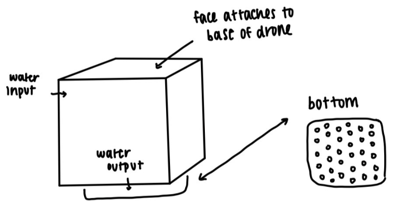
First Design: This concept involved two stacked boxes with staggered holes. The upper box had holes at the bottom, and the lower box had holes at the top. When the boxes were shifted, water would be released in a pattern simulating rainfall.
Second Design: This design featured a water storage box with a trap door at the bottom. Upon detecting a wildfire, the drone would trigger the trap door to release all the water at once, targeting the fire directly.
Third Design: Similar to the first, this design used two boxes, but the top box was significantly larger. Water would flow from the top box to the bottom box, which had holes to distribute the water evenly, simulating rainfall.
Fourth Design: This solution comprised a two-part system attached to the drone. The top part connected to the drone, while the bottom part held four fire suppressant boxes. A servo mechanism would release the boxes onto the fire when the drone was in position.
After careful evaluation, the fourth solution was selected for further development. The team identified several concerns with the mechanics of the first three designs, leading to uncertainty about their feasibility. The fourth design stood out for its uniqueness and provided a clearer understanding of the mechanical operation, making it the preferred choice for finalization.


FIRE SUPPRESSION SYSTEM ITERATION 1
To initiate the building process, the Fire Suppression Subsystem was selected for 3D printing, starting with the creation of a CAD rendering. Initially, Rhino 7 was used, but we transitioned to OnShape due to its ability to input precise dimensions earlier in the process. Unlike Rhino, which applies dimensions at the end, OnShape allowed for greater accuracy from the outset.
The first version focused on designing and printing the bottom section and attachment piece to test compatibility with the servo. Once confirmed, the top section, which connects to the drone frame, was designed and printed.
However, when attempting to fit the servo in the center, the team encountered difficulties and also wanted to reduce the overall weight of the piece.


FIRE SUPPRESSION SYSTEM ITERATION 2
For the next iteration, the walls of the base were made thinner, and all sections of it were hollowed out. Two indents were also added to create more space for the servo in the center section.
Although this iteration was significantly lighter than the first, dimensional issues remained—specifically, the servo still didn’t fit, and the walls were not as thin as desired in some areas. The team also identified a simpler, more efficient design approach. Instead of having two separate parts (the top connecting to the drone and the bottom holding the four boxes), the top part was eliminated, and two columns were added to the bottom section. This allowed the Fire Suppression System to be 3D printed in one piece, with the columns attaching directly to the drone frame. These adjustments were applied in the next iteration, shown below.
FIRE SUPPRESSION SYSTEM ITERATION 3
This next version was much better compared to the ones before it. However, there were still some issues present. The two columns had to be shifted over approximately 20mm and the dimensions for the center section (that holds the servo) needed to be 18 x 23mm.


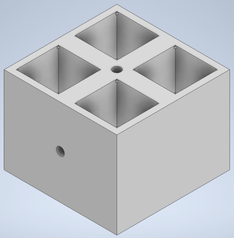
FIRE SUPPRESSION SYSTEM FINAL ITERATION
Once these modifications were made, the updated rendering was printed, resulting in the team's finalized base design, as shown below. After completing this final iteration, a servo was installed in the center. The servo actuates a plate that releases fire suppressant-filled boxes when triggered. It was tested by attaching the servo, turning it on, and creating a signal to control it. This signal moves the servo to an "open" position, 45 degrees from its default, releasing the boxes. With the servo in place, the attachment was added on top.
With the base complete, the next step was to create the four boxes. These were made from wax paper and filled with small pieces of paper to simulate the fire suppressant. Wax paper was chosen due to its degradability and environmental safety. Being a combination of paper and wax, it burns easily without releasing harmful particulates. When deployed onto a wildfire, the paper burns, and the fire extinguishes upon contact with the suppressant.
For the suppressant, research into dry powder fire extinguishers revealed their versatility for various fire types, making them suitable for outdoor wildfires (Fire Risk Assessment Network, 2021).


ELECTRONIC SYSTEM DESIGN
The electronics subsystem was designed to meet specifications for detecting atmospheric conditions (smoke, heat), monitoring faults, transmitting telemetry, and avoiding obstacles. The Arduino Nano 3 was selected for its compact size, lightweight design, and ability to operate at 3.3V or 5V, with 11 digital pins—4 for PWM and 7 for sensors.
A finite state machine was created to manage operations, integrating a heat-seeking algorithm, geolocation, and sensor accuracy. Testing confirmed the system’s capability to guide the drone to fire-affected areas and maintain communication with the base station.
To fit the 11 required data pins, I2C was used for the gyroscope and infrared sensor, sharing 2 pins by assigning unique addresses. The remaining sensors were allocated individual pins.
The PCB, sized 100mm x 60mm, features thicker traces for high power needs and capacitors to reduce electrical noise. It includes one XT-60 connector for power and four XT-30 connectors for ESCs. A 5V regulator powers the Arduino, with 3.3V sensors positioned near the Arduino’s 3.3V pin.
The autonomous control system allows the drone to ascend, navigate using GPS and gyroscope data, and reach target areas. It sweeps for smoke, uses an infrared sensor to detect fires, and releases suppressant as needed. Safety features include automatic return on low battery, temperature sensors to prevent overheating, and a low-power beacon mode if the drone is lost.

ELECTRONIC SYSTEM BUILD
The PCB construction was mostly straightforward, as the main requirement was soldering all the components. However, due to time constraints, four traces were missed during the design, requiring the pins to be manually soldered together. This was done successfully, and all connections were made properly.

PROPULSION SYSTEM DESIGN
Designing the propulsion subsystem aimed for a lightweight, fast drone with a high thrust-to-weight ratio. RS2205 motors and HQ4045 propellers were selected to achieve the necessary thrust for a 3 lb drone, ensuring reliable takeoff. The frame required four motors—two spinning counterclockwise and two clockwise—with five-inch shields on each propeller for safety.
The goal was a fully autonomous drone capable of lifting off, flying to a specific location, and returning. A comprehensive control system using sensor data was needed, with a PID controller planned for flight stabilization. However, the lack of a key event trigger impacted its implementation.
For power, a 12V supply was chosen over lithium-ion batteries for safety. This supply meets the 3-4S LiPo voltage range (11.1V to 14.8V) required by the motors and powers the Arduino Nano and sensors. A 12V 100 Amp power supply was selected after a load calculation determined the maximum current draw and accounted for potential spikes.
Finally, four ESCs rated for 30 amps were selected, each handling up to 20 amps from the motors. These ESCs were compatible with the Arduino Nano’s PWM signals for effective motor control.


PROPULSION SYSTEM BUILD
The construction of the propulsion subsystem was straightforward. The ESCs connected directly to the PCB for power, motors plugged into the ESCs, and propellers were attached to the motors with nuts. The frame featured screw holes for mounting the motors and clasps on the propeller shields for secure attachment.
Motors were placed according to their designated positions, ensuring proper orientation. Components and wires were secured to the frame with zip ties and electrical tape, and wires were carefully shortened to prevent tangling.

HUB SYSTEM DESIGN & ITERATION 1
All designs were made in Inventor Studio and 3D printed. The only assembly required was to glue the screw to the motor. The initial design for the hub system involved a water-pumped mechanism where magnetic hoses would connect to the fire suppression system and refill it with water when the drone landed for recharging. This design was ultimately replaced with a simpler and more practical solution.

HUB SYSTEM ITERATION 2
The second model featured a locking mechanism at the bottom of the fire suppression system. This required the storage compartment's top to be flush and the platform lifting the fire suppression units to align with the top surface. The design also included strings wound and unwound by a stepper motor to lift and lower the suppressant.
Due to uncertainties with 3D printing, this design was abandoned. Instead, the locking mechanism was moved to the top of the system, simplifying both the design and loading process.


HUB SYSTEM FINAL ITERATION
The final iteration employs a screw mechanism to lift and drop the fire suppressant units. With the locking mechanism positioned at the top of the system, the platform extends outward rather than being flush with the storage top to allow the cubes to reach it. A centrally located screw, driven by a motor enclosed in a shell, rotates to lift the suppression units into the chassis for reloading. The motor is programmed to rotate the necessary number of times to move the units into position.


FINAL PRODUCT
With the five subsystems complete, the last step is to combine all the pieces together.

To learn more about the design and prototyping process for this project, please visit this link:
https://drive.google.com/file/d/1ICLgFscN20kYYnvL5IyUHbYkrPCyHtL3/view?usp=sharing